PB Heat DE User Manual
Browse online or download User Manual for Water heaters & boilers PB Heat DE. PB Heat DE User's Manual
- Page / 43
- Table of contents
- TROUBLESHOOTING
- BOOKMARKS
- Installation 1
- Operation & 1
- Maintenance 1
- TABLE OF CONTENTS 2
- USING THIS MANUAL 3
- 1. PREINSTALLATION 4
- PREINSTALLATION 5
- 2. BOILER SET-UP 8
- 3. WATER PIPING AND CONTROLS 9
- WATER PIPING AND CONTROLS 10
- 4. VENTING 13
- E. BOILER REMOVAL FROM COMMON 17
- VENTING SYSTEM 17
- 5. GAS PIPING 18
- GAS PIPING 19
- 6. ELECTRICAL 20
- ELECTRICAL 21
- 7. START-UP PROCEDURES 24
- START-UP PROCEDURES 25
- OPERATING INSTRUCTIONS 26
- TO TURN OFF GAS TO APPLIANCE 26
- 8. TROUBLESHOOTING 30
- TROUBLESHOOTING 31
- 9. MAINTENANCE 34
- MAINTENANCE 35
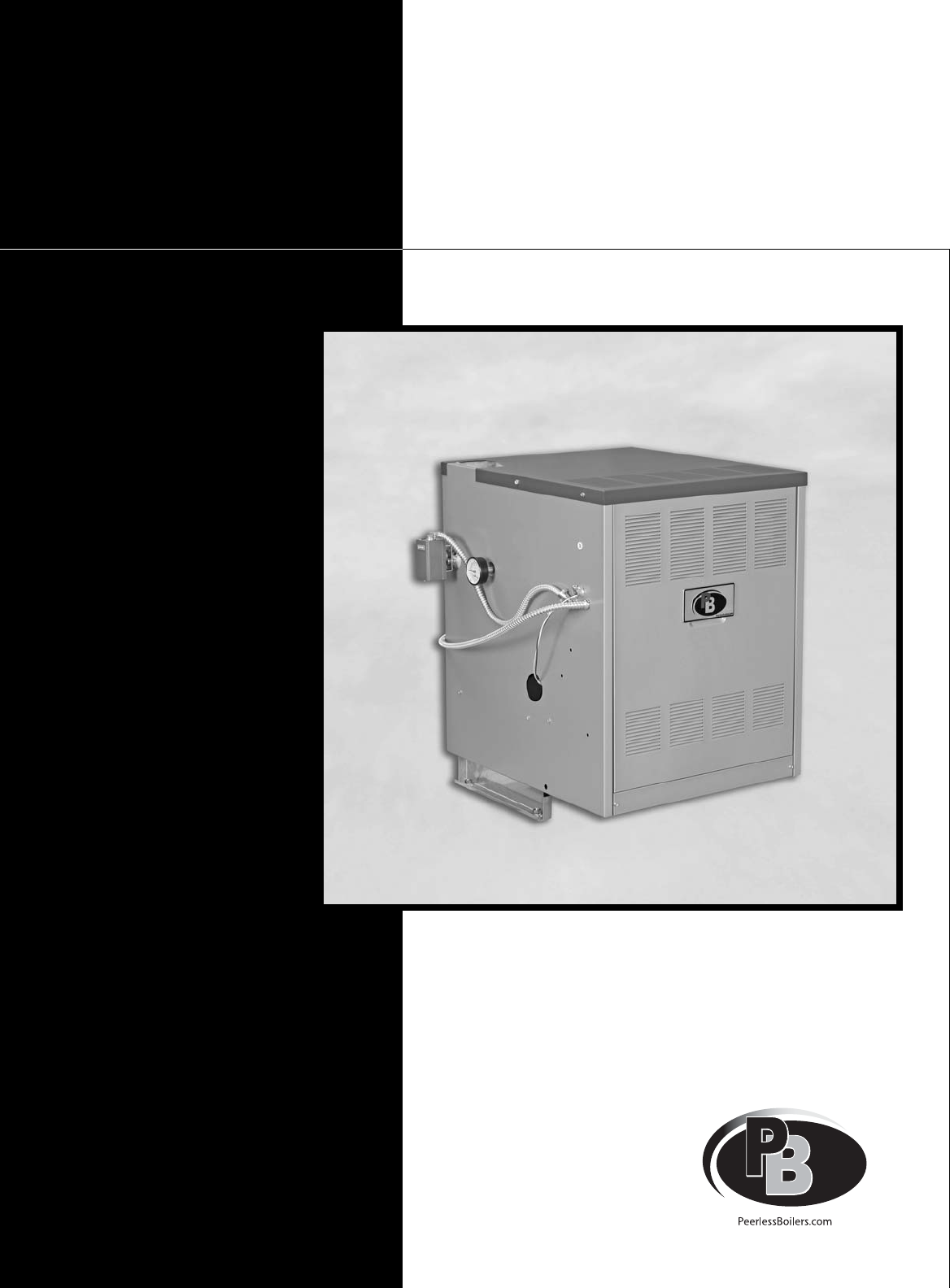
- Figure 10.1: Boiler Views 37
- SERIES DE BOILER RATINGS 37
- REPAIR PARTS 38
- SERIES DE GAS BOILER 38
- 11. REPAIR PARTS 38
Summary of Contents
DEBoilersSeriesGasInstallation,Operation &MaintenanceManual
86. Install this boiler so that the gas ignition systemcomponents are protected from water (dripping,spraying, etc.) during appliance operation andser
9C. PIPING FOR ZONED SYSTEMS1. See Figures 3.5 and 3.6 for basic zoned systemlayouts.2. Run each zone pipe down then up to zone toprevent air accumula
10D. EXPANSION TANK1. Consult the tank manufacturer’s instructions forspecific information relating to tank installation. Sizethe expansion tank for t
11A. GENERAL1. Install vent system in accordance with the "Ventingof Equipment" Chapter of the National Fuel GasCode, ANSI Z223.1/NFPA 54,
122. Refer to Table 4.2 for minimum and maximum ventlength allowed.3. Maintain a minimum 2” (51 mm) clearance betweenvent pipe and combustible constru
13VENTINGFigure 4.2: Direct Exhaust, Sidewall Venting with Vertical Off-SetFigure 4.3: Vent Pipe Adapters
14D. DIRECT EXHAUST; VERTICAL VENTING1. This vent system will operate with a positive pressurein the vent pipe. Follow vent pipe manufacturer’sinstruc
15VENTINGE. BOILER REMOVAL FROM COMMONVENTING SYSTEMAt the time of removal of an existing boiler, follow thesesteps with each appliance remaining conn
161. Size and install the gas supply piping properly inorder to provide a supply of gas sufficient to meetthe maximum demand without undue loss ofpres
17Table 5.3: Pipe CapacityCapacity of pipe of different diameters and lengths in cubic feet per hour[cubic meter per hour] with a pressure drop of 0.3
iiUSING THIS MANUAL 1A. INSTALLATION SEQUENCE . . . . . . . . . . . . .1B. SPECIAL ATTENTION BOXES . . . . . . . . . . . .11. PREINSTALLATION 2A. AC
18A. WIRING1. See Figure 6.1 for location of wiring and controls.Use Figure 6.2 to connect the boiler to a powersupply and to connect components to th
19D. SEQUENCE OF OPERATION1. Thermostat calls for heat, energizes Control Relay(CR).2. Control Relay (CR) energizes circulator.3. Limit senses boiler
20Figure 6.3: Ignition System Operating SequenceELECTRICAL
21ELECTRICALFigure 6.4: Zone Wiring with Zone ValvesFigure 6.5: Zone Wiring with Circulators
22A. COMPLETING THE INSTALLATION1. Confirm that all water, gas and electricity areturned off.2. Inspect the boiler combustion chamber for foreignobjec
23Figure 7.1: Gas Valve, Manifold and Burner Assembly – Intermittent IgnitionFigure 7.2: Valve Tapping and Adjustment Screw LocationsSTART-UP PROCEDUR
24START-UP PROCEDURESFigure 7.3: Operating InstructionsSV9501/SV9601 9318 REV 2 (MM/YY)FOR YOUR SAFETY READ BEFORE LIGHTINGWARNING: If you do not fol
25B. CONTROL DESCRIPTIONSSee Figure 6.1 in Section 6 (Electrical) for locations ofthese devices.1. FLAME ROLL-OUT SAFETY SHUT-OFF SWITCH(FLAME ROLL-OU
26E. CHECK-OUT PROCEDURE1. After starting the boiler, be certain all controls areworking properly. Check to be sure that the limit willshut off the bo
273. Low Water Cut-Off (if used) – Consult themanufacturer’s instructions for the low water cut-offoperational check procedure.4. Check the system to
1A. INSTALLATION SEQUENCEFollow the installation instructions provided in thismanual in the order shown. The order of theseinstructions has been set i
28A. SHUT-DOWN CAUSED BY PILOT OUTAGE, PRESSURE SWITCH ORFLAME ROLL-OUT SAFETY SHUT-OFF SWITCHIn the event of a shut-down caused by a pilot outage,act
29TROUBLESHOOTINGFigure 8.1: Procedure For Measuring Fan Suction PressureSEE TABLE 7
30TROUBLESHOOTINGTable 8.2: Boiler Troubleshooting Guide (Burners Functioning)Problem Possible Causes Corrective Actions1. See Figure 8.2Burners not f
31Figure 8.2: Boiler Troubleshooting Guide (Burners Not Functioning)TROUBLESHOOTING
32MAINTENANCE9. MAINTENANCEWARNINGProduct Safety InformationRefractory Ceramic Fiber ProductThis appliance contains materials made from refractory cer
33A. GENERAL1. Disconnect this boiler from the gas supply pipingduring any pressure testing of the gas system.2. Check pipes adjacent to cold walls o
34E. ANNUALLY (BEFORE START OF HEATINGSEASON)1. Check flueways and burners for cleanliness andclean if necessary. Use the following procedure ifcleani
35BOILER DIMENSIONS & RATINGS10. BOILER DIMENSIONS & RATINGSFigure 10.1: Boiler ViewsTable 10.1: Series DE Boiler Ratings1 Net I=B=R water rat
36REPAIR PARTSFigure 11.1: Block/Base/Floor Pan/Jacket/Flue CollectorREPAIR PARTSSERIES DE GAS BOILERRepair parts are available from your installer or
37REPAIR PARTSFigure 11.2: Base/Burners/Manifold
2A. ACCESSIBILITY CLEARANCESInstall boiler not less than 24″ (610 mm) between the leftside, top, and front of the boiler and adjacent wall orother app
38REPAIR PARTSTable 11.1: Repair Parts1234567891011121314151617Block AssemblyBase AssemblyObservation Cover DoorBase Blanket SealCombustible Floor Pan
39NOTES
DEBoilersSeriesGasInstallation,Operation &MaintenanceManualTO THE INSTALLER:This manual is the property of the owner and mustbe affixed near the b
3where:Ifan= Input of the fan assisted appliances inBtu/hrACH = air change per hour (percent of thevolume of the space exchanged perhour, expressed as
4ii. Where communicating with the outdoorsthrough horizontal ducts, each opening shallhave a minimum free area of 1 in2per 2000Btu/hr (22 cm2per 2000
5c. Each of the appliances served shall beinterlocked to the mechanical air supply toprevent main burner operation where themechanical air supply syst
6BOILER SET-UP1. Provide a sound, level foundation. Locate boiler asnear to the chimney or outside wall as possible andcentralized with respect to the
7A. BOILER SUPPLY AND RETURN1. Size the supply and return to suit the system. Atypical piping arrangement is shown in Figure 3.1.Refer also to the I=B
Related products and manuals for Water heaters & boilers PB Heat DE
 (27 pages)
© 2020, manymanuals.com. All rights reserved. | 0.893 s |
 Manymanuals.com
 Manymanuals.de
 Manymanuals.fr
 Manymanuals.it
 Manymanuals.pl
 Manymanuals.cz
 Manymanuals.es
 Manymanuals-pt.com
Comments to this Manuals